Thursday, April 15, 2010

Spherical Terrain Physics

For quite a long while I have been trying to figure out how exactly to do collision detection on my procedurally generated, tessellated, spherical terrain.

The problem lies with the fact that terrain itself doesn't really exist until the GPU. I generate a simple spherical mesh on the CPU and then send it to the GPU to draw. Once there it is tessellated based upon the distance to the camera and then it is displaced via a summation of Perlin Noise.

Obviously this makes it very hard to do collision detection on the CPU side. Many physics engines support a special heightmap object for terrain, but they all assume the terrain is on a plane (usually the XZ) with one axis being the displacement axis (usually the Y). Of course that wouldn't work for spherical terrain. Most physics engines also have a generic triangle mesh object. However these are usually meant to be static meshes and therefore are hard to tessellate. It would require destroying and recreating a mesh on the fly, which would be rather slow and wasteful.

What I really needed was the ability to create a collision shape that was defined by an equation (the Perlin sum in my case). In the past I have always used PhysX, but since it is closed source I decided to try this out in another physics engine. I hopped onto the Bullet forums and posed the question. I was told that it should be possible if I created a new shape object that inherited from the base concave object and overrode its ProcessAllTriangles() method to use the equation.

So, I went and did exactly that. Lo and behold it worked!

First, I created a shape called btSphericalTerrainShape which inherits from btConcaveShape. It takes 3 parameters to setup: The center point of the terrain, the radius of the terrain (including the maximum offset of the terrain) which is used for the bounding box, and a function pointer that points to a function that defines the terrain's equation.

btSphericalTerrainShape(const btVector3& center, btScalar radius, btVector3 (*calcVertex)(const btVector3& position, const btVector3& center));


The function pointer passes along 2 parameters: the current point being evaluated (usually one of the corners of the other object's bounding box), and the center point of the terrain. This allows the terrain to be defined by practically any method desired.

For example, if you wanted to define the terrain as a simple sphere with a radius of 50, you would use the following method:

btVector3 calculateTerrainVertex(const btVector3& position, const btVector3& center)
{
    return (position - center).normalized() * 50.0f;
}


If you wanted to define the terrain as a sphere with a radius of 50 that was offset by 8 octaves of Perlin Noise, you would use this method:

btVector3 calculateTerrainVertex(const btVector3& position, const btVector3& center)
{
    btVector3 normalized = (position - center).normalized();
    double result = PerlinNoise::fBm(normalized.x(), normalized.y(), normalized.z(), 8);
    return normalized * btScalar(50.0f + result * 10.0);
}


Now, for the details on the ProcessAllTriangles() method. It takes an axis aligned bounding box (AABB) for the other shape being tested and a callback that is called for each triangle that collides with that bounding box.

These are the steps done in the method:

1) Calculate the 8 corners of the AABB
2) Calculate the midpoint of each of the 6 sides of the AABB
3) Calculate the position of the vertex on the terrain by calling the calculateTerrainVertex function pointer
4) Determine which of the corners of the AABB are colliding with the terrain by checking if the bounding box corners are closer to the center point than the respective terrain vertices
5) Find which 3 sides of the AABB are closest to the terrain in order to prevent extraneous triangle processing
6) Use the callback to process each triangle that collides

For the actual implementation details, be sure to download the source code for the btSphericalTerrainShape.

btSphericalTerrainShape.h
btSphericalTerrainShape.cpp

Thursday, April 8, 2010

Sobel Filter Compute Shader

Thanks to Josh Petrie, I now have the Compute Shader working with the swap chain backbuffer. I decided a good first test is to use a Compute Shader to run a Sobel Filter on an image and display the result in the backbuffer.

It was all very easy to get set up. First you create a DirectX 11 swap chain, just like normal. The only difference is the Usage property of the swap chain has an additional flag set which is (Usage)1024 and it represents UnorderedAccess. This allows the backbuffer to be used as an output UAV in the Compute Shader.


RenderForm form = new RenderForm("SlimDX - Sobel Filter Compute Shader");
form.ClientSize = new Size(1024, 1024);

SwapChainDescription swapChainDesc = new SwapChainDescription()
{
    BufferCount = 1,
    Flags = SwapChainFlags.None,
    IsWindowed = true,
    ModeDescription = new ModeDescription(form.ClientSize.Width, form.ClientSize.Height, new Rational(60, 1), Format.R8G8B8A8_UNorm),
    OutputHandle = form.Handle,
    SampleDescription = new SampleDescription(1, 0),
    SwapEffect = SwapEffect.Discard,
    //(Usage)1024 = Usage.UnorderedAccess
    Usage = Usage.RenderTargetOutput | (Usage)1024 
};
 

Device device;
SwapChain swapChain;
Device.CreateWithSwapChain(null, DriverType.Hardware, DeviceCreationFlags.Debug, swapChainDesc, out device, out swapChain);


The rest of the setup is standard stuff. You grab the backbuffer texture, load the image to run the filter on, and load/compile the Compute Shader.

Texture2D backBuffer = Texture2D.FromSwapChain<Texture2D>(swapChain, 0);
RenderTargetView renderView = new RenderTargetView(device, backBuffer);
 
Texture2D flower = Texture2D.FromFile(device, "flower.jpg");
ShaderResourceView resourceView = new ShaderResourceView(device, flower);
 
ComputeShader compute = Helper.LoadComputeShader(device, "Sobel.hlsl", "main");
UnorderedAccessView computeResult = new UnorderedAccessView(device, backBuffer);


The "render" loop doesn't contain any actual rendering. It sets up the render target and viewport like normal, but then it sets the Compute Shader and runs it. After the Compute Shader is ran, the swap chain is told to present the backbuffer, which now contains the Compute Shader output.

device.ImmediateContext.OutputMerger.SetTargets(renderView);
device.ImmediateContext.Rasterizer.SetViewports(new Viewport(0, 0, form.ClientSize.Width, form.ClientSize.Height, 0.0f, 1.0f));
 
MessagePump.Run(form, () =>
{
    device.ImmediateContext.ClearRenderTargetView(renderView, Color.Black);
 
    device.ImmediateContext.ComputeShader.Set(compute);
    device.ImmediateContext.ComputeShader.SetShaderResource(resourceView, 0);
    device.ImmediateContext.ComputeShader.SetUnorderedAccessView(computeResult, 0);
    device.ImmediateContext.ComputeShader.SetConstantBuffer(constantBuffer, 0);
    device.ImmediateContext.Dispatch(32, 32, 1);
 
    swapChain.Present(0, PresentFlags.None);
});


That's it for the CPU side, now let's look at the GPU side. It's a standard Sobel Filter that only has an input texture and an output texture. The output can either be the Sobel result alone, or it can be the Sobel result laid over the input texture.


Texture2D Input : register(t0);
RWTexture2D Output : register(u0);

[numthreads(32, 32, 1)]
void main( uint3 threadID : SV_DispatchThreadID )
{
float threshold = 0.20f;
bool overlay = true;

// Sample neighbor pixels
// 00 01 02
// 10 __ 12
// 20 21 22
float s00 = Input[threadID.xy + float2(-1, -1)].r;
float s01 = Input[threadID.xy + float2( 0, -1)].r;
float s02 = Input[threadID.xy + float2( 1, -1)].r;
float s10 = Input[threadID.xy + float2(-1, 0)].r;
float s12 = Input[threadID.xy + float2( 1, 0)].r;
float s20 = Input[threadID.xy + float2(-1, 1)].r;
float s21 = Input[threadID.xy + float2( 0, 1)].r;
float s22 = Input[threadID.xy + float2( 1, 1)].r;

float sobelX = s00 + 2 * s10 + s20 - s02 - 2 * s12 - s22;
float sobelY = s00 + 2 * s01 + s02 - s20 - 2 * s21 - s22;

float edgeSqr = (sobelX * sobelX + sobelY * sobelY);
float result = 1.0 - (edgeSqr > threshold * threshold); //white background, black lines
Output[threadID.xy] = result;
if (overlay && result != 0.0)
Output[threadID.xy] = Input[threadID.xy];
}


That's it! I already improved the code so that the threshold float and overlay boolean are in a constant buffer that is set on the CPU side, but I figured I'd keep the code posted here as simple as I could.

Here was my input image:


And here is the the output image (input + Sobel result overlay):


Nothing too spectacular, but the main focus was the Compute Shader + backbuffer, not the actual Sobel Filter. Enjoy!

By the way, you may have noticed that my C# code snippets now use the same syntax highlighting as Visual Studio. I installed the CopySourceAsHtml add-on and it seems to work pretty well.

Wednesday, April 7, 2010

SlimDX Issue

In my previous post I mentioned how my next goal was to use the Compute Shader to write directly to the backbuffer. Unfortunately, it appears that this is not currently possible using SlimDX.

In order to write to the backbuffer, the swap chain needs to be created with an unordered access usage flag. This means that that resource can then be used as a UAV output in a Compute Shader. There are a couple examples floating around online where people have done this using the DXGI_USAGE_UNORDERED_ACCESS flag in C++ code.

In SlimDX, that enumeration has been wrapped into the Usage enumeration in the DXGI namespace. However, it is missing an UnorderedAccess option. It contains all of the other ones defined in the original C++ code though. I believe it was just a mistake and accidentally missed during the update to DX11. (At least I hope it wasn't intentional!)

I posted an issue on the SlimDX Google Code page, so hopefully this gets resolved.

Sunday, April 4, 2010

Simple Compute Shader Example

The other big side of DirectX 11 is the Compute Shader. I thought I would write up a very simple example along the same lines as my tessellation example.

First let me say that the Compute Shader is awesome! It opens up so many possibilities. My mind is just reeling with new ideas to try out. Also I must mention that SlimDX really does a great job of minimalizing the code necessary to use the Compute Shader.

This example shows how to create a Compute Shader and then use it to launch threads that simply output the thread ID to a texture.

Device device = new Device(DriverType.Hardware, DeviceCreationFlags.Debug, FeatureLevel.Level_11_0);
 
ComputeShader compute = Helper.LoadComputeShader(device, "SimpleCompute.hlsl", "main");
 
Texture2D uavTexture;
UnorderedAccessView computeResult = Helper.CreateUnorderedAccessView(device, 1024, 1024, Format.R8G8B8A8_UNorm, out uavTexture);
 
device.ImmediateContext.ComputeShader.Set(compute);
device.ImmediateContext.ComputeShader.SetUnorderedAccessView(computeResult, 0);
device.ImmediateContext.Dispatch(32, 32, 1);
 
Texture2D.ToFile(device.ImmediateContext, uavTexture, ImageFileFormat.Png, "uav.png");


Believe it or not, but that is the entirety of my CPU code.

Here is what is going on in the code:
1) Create a feature level 11 Device, in order to use Compute Shader 5.0
2) Load/Compile the HLSL code into a ComputeShader object.
3) Create a 1024x1024 UnorderedAccesdView (UAV) object which will be used to store the output.
4) Set the ComputeShader and UAV on the device.
5) Run the Compute Shader by calling Dispatch (32x32x1 thread groups are dispatched).
6) Save the output texture out to disk.

My HLSL code is even simpler:

RWTexture2D<float4> Output;

[numthreads(32, 32, 1)]
void main( uint3 threadID : SV_DispatchThreadID )
{
Output[threadID.xy] = float4(threadID.xy / 1024.0f, 0, 1);
}


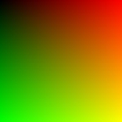
As you can see a RWTexture2D object is used to store the output (this is the UAV). The shader is setup to run 32x32x1 threads. This means that since the CPU is launching 32x32x1 thread groups, then there are 1024x1024x1 separate threads being run. This equates to 1 thread per pixel in the output UAV. So, in the UAV, the color is just set based upon the thread ID.

This code results in the following output image:


Quite simple, eh? But not that interesting. We could easily do something like that with a pixel shader (although we would have to rasterize a full-screen quad to do it).

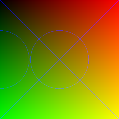
We should try to do something that shows the power of the compute shader; something you couldn't do in a pixel shader before. How about drawing some primitives like lines and circles?

For drawing lines, let's use the Digital Differential Analyzer algorithm. It translates to HLSL very easily.


void Plot(int x, int y)
{
Output[uint2(x, y)] = float4(0, 0, 1, 1);
}

void DrawLine(float2 start, float2 end)
{
float dydx = (end.y - start.y) / (end.x - start.x);
float y = start.y;
for (int x = start.x; x <= end.x; x++)
{
Plot(x, round(y));
y = y + dydx;
}
}


For drawing circles let's use the Midpoint Circle algorithm. For brevity I won't list it here now.

Then, in my Compute Shader main function, I simply add this code:

if (threadID.x == 1023 && threadID.y == 1023)
{
DrawLine(float2(0, 0), float2(1024, 1024));
DrawLine(float2(0, 1023), float2(1023, 0));

DrawCircle(512, 512, 250);
DrawCircle(0, 512, 250);
}


The if check is just done to prevent the lines and circles from being drawn for every thread. This code results in the following image:


I must admit it seems quite odd writing a shader that draws primitives. It's like some strange recursive loop. But it definitely helps to illustrate the features of the Compute Shader and how powerful it is.

You may download the source code to this example here:
ComputeShader11.zip

My next goal is to setup a standard DX11 Swap Chain and use the Compute Shader to write directly to the backbuffer. Well that's all for now.

FYI: This is my 50th blog post! I never thought I would continue on this long. I think I should crack open a beer to celebrate.