Wow! I can't really believe it's been 7 months (exactly!) since I last posted an entry here. I wish I had something to show, but sadly I do not. To be honest, I have been all over the place with my development. I experimented with a number of different things, but nothing for an extended period of time. I'm hoping to change that soon though. More on that later, first a list of the things I was working on:
Shadow Mapping
I had actually never done any shadow mapping programming before, so it was more of a learning experience in understanding the concept and what is required. I implemented a simple demo in SlimDX/DirectX 11 and posted a video of it on YouTube, but it really is nothing exciting. Standard, run of the mill, shadow mapping. No fancy tricks in the implementation.
Parallel City Generation
I pulled out the old procedural city generator code I blogged about before and updated and refactored the road generator to be able to run in parallel. This allowed me to draw the roads as they were being created. I thought it was pretty cool looking. My goal was to parallelize it to the point where I could implement it as a compute shader, but I couldn't seem to get it to that point. So, I kind of gave up on it.
Bullet Physics
I decided to go back and start messing around with physics again, and I used XNA and BulletSharp this time. I was working on an idea that I've had brewing in the back of my brain for quite awhile. I made some decent progress and was quite happy. However, I started thinking about how I was essentially writing my own game engine (terrain, lighting, shadowing, physics integration). Plus, looking at the target platforms for XNA (Xbox 360, Windows Desktop, Windows Phone), I started wondering if that was best for me. So, that led me to the next item.
Unity
For several months Unity had been looking appealing to me. Two of the biggest pulls for me were C# scripting (via the Mono Framework) and PhysX integration. The wide array of supported platforms was also a huge plus (Mac, Windows, iPhone, iPad, Web). When they announced support for Android as well, I was "sold" in a manner of speaking (as I have an Android phone myself). So, I installed the free version of Unity and tried to see if I could implement the functionality I had already implemented via BulletSharp and XNA inside of Unity scripting itself. One weekend later, I had accomplished that and more!
I'll be honest, Unity is far from the perfect engine. It severely limits you due to the wide range of hardware specs that it runs on. Don't expect to be doing any tessellation or compute shaders here. Heck, it doesn't even support geometry shaders! However, it does seem to be a very well organized engine with good documentation on their webpage and a component based system that I love. I like it enough to at least fiddle around with it some more over the next couple of months.
An added bonus is that my prototypes can be deployed to my server which means you (the reader) can run them in your browser without installing the them. Expect to see a Perlin Noise example soon. :-) That really has become my "Hello World" program for testing different graphics APIs.
A final note I'd like to leave here is regarding some other "big" game engines. I was slightly surprised last week to hear not just one, but two game engines have essentially "imploded". Both Torque and Gamebryo are closing up shop and looking for buyers. That leaves Unity looking even stronger.
Until next time!
Monday, November 15, 2010
Thursday, April 15, 2010
Spherical Terrain Physics
For quite a long while I have been trying to figure out how exactly to do collision detection on my procedurally generated, tessellated, spherical terrain.
The problem lies with the fact that terrain itself doesn't really exist until the GPU. I generate a simple spherical mesh on the CPU and then send it to the GPU to draw. Once there it is tessellated based upon the distance to the camera and then it is displaced via a summation of Perlin Noise.
Obviously this makes it very hard to do collision detection on the CPU side. Many physics engines support a special heightmap object for terrain, but they all assume the terrain is on a plane (usually the XZ) with one axis being the displacement axis (usually the Y). Of course that wouldn't work for spherical terrain. Most physics engines also have a generic triangle mesh object. However these are usually meant to be static meshes and therefore are hard to tessellate. It would require destroying and recreating a mesh on the fly, which would be rather slow and wasteful.
What I really needed was the ability to create a collision shape that was defined by an equation (the Perlin sum in my case). In the past I have always used PhysX, but since it is closed source I decided to try this out in another physics engine. I hopped onto the Bullet forums and posed the question. I was told that it should be possible if I created a new shape object that inherited from the base concave object and overrode its ProcessAllTriangles() method to use the equation.
So, I went and did exactly that. Lo and behold it worked!
First, I created a shape called btSphericalTerrainShape which inherits from btConcaveShape. It takes 3 parameters to setup: The center point of the terrain, the radius of the terrain (including the maximum offset of the terrain) which is used for the bounding box, and a function pointer that points to a function that defines the terrain's equation.
The function pointer passes along 2 parameters: the current point being evaluated (usually one of the corners of the other object's bounding box), and the center point of the terrain. This allows the terrain to be defined by practically any method desired.
For example, if you wanted to define the terrain as a simple sphere with a radius of 50, you would use the following method:
If you wanted to define the terrain as a sphere with a radius of 50 that was offset by 8 octaves of Perlin Noise, you would use this method:
Now, for the details on the ProcessAllTriangles() method. It takes an axis aligned bounding box (AABB) for the other shape being tested and a callback that is called for each triangle that collides with that bounding box.
These are the steps done in the method:
1) Calculate the 8 corners of the AABB
2) Calculate the midpoint of each of the 6 sides of the AABB
3) Calculate the position of the vertex on the terrain by calling the calculateTerrainVertex function pointer
4) Determine which of the corners of the AABB are colliding with the terrain by checking if the bounding box corners are closer to the center point than the respective terrain vertices
5) Find which 3 sides of the AABB are closest to the terrain in order to prevent extraneous triangle processing
6) Use the callback to process each triangle that collides
For the actual implementation details, be sure to download the source code for the btSphericalTerrainShape.
btSphericalTerrainShape.h
btSphericalTerrainShape.cpp
The problem lies with the fact that terrain itself doesn't really exist until the GPU. I generate a simple spherical mesh on the CPU and then send it to the GPU to draw. Once there it is tessellated based upon the distance to the camera and then it is displaced via a summation of Perlin Noise.
Obviously this makes it very hard to do collision detection on the CPU side. Many physics engines support a special heightmap object for terrain, but they all assume the terrain is on a plane (usually the XZ) with one axis being the displacement axis (usually the Y). Of course that wouldn't work for spherical terrain. Most physics engines also have a generic triangle mesh object. However these are usually meant to be static meshes and therefore are hard to tessellate. It would require destroying and recreating a mesh on the fly, which would be rather slow and wasteful.
What I really needed was the ability to create a collision shape that was defined by an equation (the Perlin sum in my case). In the past I have always used PhysX, but since it is closed source I decided to try this out in another physics engine. I hopped onto the Bullet forums and posed the question. I was told that it should be possible if I created a new shape object that inherited from the base concave object and overrode its ProcessAllTriangles() method to use the equation.
So, I went and did exactly that. Lo and behold it worked!
First, I created a shape called btSphericalTerrainShape which inherits from btConcaveShape. It takes 3 parameters to setup: The center point of the terrain, the radius of the terrain (including the maximum offset of the terrain) which is used for the bounding box, and a function pointer that points to a function that defines the terrain's equation.
btSphericalTerrainShape(const btVector3& center, btScalar radius, btVector3 (*calcVertex)(const btVector3& position, const btVector3& center));
The function pointer passes along 2 parameters: the current point being evaluated (usually one of the corners of the other object's bounding box), and the center point of the terrain. This allows the terrain to be defined by practically any method desired.
For example, if you wanted to define the terrain as a simple sphere with a radius of 50, you would use the following method:
btVector3 calculateTerrainVertex(const btVector3& position, const btVector3& center)
{ return (position - center).normalized() * 50.0f;}
If you wanted to define the terrain as a sphere with a radius of 50 that was offset by 8 octaves of Perlin Noise, you would use this method:
btVector3 calculateTerrainVertex(const btVector3& position, const btVector3& center)
{btVector3 normalized = (position - center).normalized();
double result = PerlinNoise::fBm(normalized.x(), normalized.y(), normalized.z(), 8); return normalized * btScalar(50.0f + result * 10.0);}
Now, for the details on the ProcessAllTriangles() method. It takes an axis aligned bounding box (AABB) for the other shape being tested and a callback that is called for each triangle that collides with that bounding box.
These are the steps done in the method:
1) Calculate the 8 corners of the AABB
2) Calculate the midpoint of each of the 6 sides of the AABB
3) Calculate the position of the vertex on the terrain by calling the calculateTerrainVertex function pointer
4) Determine which of the corners of the AABB are colliding with the terrain by checking if the bounding box corners are closer to the center point than the respective terrain vertices
5) Find which 3 sides of the AABB are closest to the terrain in order to prevent extraneous triangle processing
6) Use the callback to process each triangle that collides
For the actual implementation details, be sure to download the source code for the btSphericalTerrainShape.
btSphericalTerrainShape.h
btSphericalTerrainShape.cpp
Thursday, April 8, 2010
Sobel Filter Compute Shader
Thanks to Josh Petrie, I now have the Compute Shader working with the swap chain backbuffer. I decided a good first test is to use a Compute Shader to run a Sobel Filter on an image and display the result in the backbuffer.
It was all very easy to get set up. First you create a DirectX 11 swap chain, just like normal. The only difference is the Usage property of the swap chain has an additional flag set which is (Usage)1024 and it represents UnorderedAccess. This allows the backbuffer to be used as an output UAV in the Compute Shader.
The rest of the setup is standard stuff. You grab the backbuffer texture, load the image to run the filter on, and load/compile the Compute Shader.
The "render" loop doesn't contain any actual rendering. It sets up the render target and viewport like normal, but then it sets the Compute Shader and runs it. After the Compute Shader is ran, the swap chain is told to present the backbuffer, which now contains the Compute Shader output.
That's it for the CPU side, now let's look at the GPU side. It's a standard Sobel Filter that only has an input texture and an output texture. The output can either be the Sobel result alone, or it can be the Sobel result laid over the input texture.
That's it! I already improved the code so that the threshold float and overlay boolean are in a constant buffer that is set on the CPU side, but I figured I'd keep the code posted here as simple as I could.
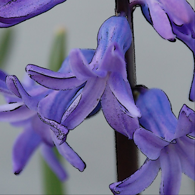
Here was my input image:

And here is the the output image (input + Sobel result overlay):
Nothing too spectacular, but the main focus was the Compute Shader + backbuffer, not the actual Sobel Filter. Enjoy!
By the way, you may have noticed that my C# code snippets now use the same syntax highlighting as Visual Studio. I installed the CopySourceAsHtml add-on and it seems to work pretty well.
It was all very easy to get set up. First you create a DirectX 11 swap chain, just like normal. The only difference is the Usage property of the swap chain has an additional flag set which is (Usage)1024 and it represents UnorderedAccess. This allows the backbuffer to be used as an output UAV in the Compute Shader.
RenderForm form = new RenderForm("SlimDX - Sobel Filter Compute Shader");
form.ClientSize = new Size(1024, 1024);
SwapChainDescription swapChainDesc = new SwapChainDescription()
{BufferCount = 1,
Flags = SwapChainFlags.None, IsWindowed = true,ModeDescription = new ModeDescription(form.ClientSize.Width, form.ClientSize.Height, new Rational(60, 1), Format.R8G8B8A8_UNorm),
OutputHandle = form.Handle,
SampleDescription = new SampleDescription(1, 0),
SwapEffect = SwapEffect.Discard, //(Usage)1024 = Usage.UnorderedAccessUsage = Usage.RenderTargetOutput | (Usage)1024
};
Device device;SwapChain swapChain;Device.CreateWithSwapChain(null, DriverType.Hardware, DeviceCreationFlags.Debug, swapChainDesc, out device, out swapChain);
The rest of the setup is standard stuff. You grab the backbuffer texture, load the image to run the filter on, and load/compile the Compute Shader.
Texture2D backBuffer = Texture2D.FromSwapChain<Texture2D>(swapChain, 0);
RenderTargetView renderView = new RenderTargetView(device, backBuffer);
Texture2D flower = Texture2D.FromFile(device, "flower.jpg");
ShaderResourceView resourceView = new ShaderResourceView(device, flower);
ComputeShader compute = Helper.LoadComputeShader(device, "Sobel.hlsl", "main");
UnorderedAccessView computeResult = new UnorderedAccessView(device, backBuffer);
The "render" loop doesn't contain any actual rendering. It sets up the render target and viewport like normal, but then it sets the Compute Shader and runs it. After the Compute Shader is ran, the swap chain is told to present the backbuffer, which now contains the Compute Shader output.
device.ImmediateContext.OutputMerger.SetTargets(renderView);
device.ImmediateContext.Rasterizer.SetViewports(new Viewport(0, 0, form.ClientSize.Width, form.ClientSize.Height, 0.0f, 1.0f));
MessagePump.Run(form, () =>{ device.ImmediateContext.ClearRenderTargetView(renderView, Color.Black);device.ImmediateContext.ComputeShader.Set(compute);
device.ImmediateContext.ComputeShader.SetShaderResource(resourceView, 0);
device.ImmediateContext.ComputeShader.SetUnorderedAccessView(computeResult, 0);
device.ImmediateContext.ComputeShader.SetConstantBuffer(constantBuffer, 0);
device.ImmediateContext.Dispatch(32, 32, 1);
swapChain.Present(0, PresentFlags.None);});
That's it for the CPU side, now let's look at the GPU side. It's a standard Sobel Filter that only has an input texture and an output texture. The output can either be the Sobel result alone, or it can be the Sobel result laid over the input texture.
Texture2D Input : register(t0);
RWTexture2D Output : register(u0);

[numthreads(32, 32, 1)]
void main( uint3 threadID : SV_DispatchThreadID )
{
    float threshold = 0.20f;
    bool overlay = true;

    // Sample neighbor pixels
    // 00 01 02
    // 10 __ 12
    // 20 21 22
    float s00 = Input[threadID.xy + float2(-1, -1)].r;
    float s01 = Input[threadID.xy + float2( 0, -1)].r;
    float s02 = Input[threadID.xy + float2( 1, -1)].r;
    float s10 = Input[threadID.xy + float2(-1,  0)].r;
    float s12 = Input[threadID.xy + float2( 1,  0)].r;
    float s20 = Input[threadID.xy + float2(-1,  1)].r;
    float s21 = Input[threadID.xy + float2( 0,  1)].r;
    float s22 = Input[threadID.xy + float2( 1,  1)].r;

    float sobelX = s00 + 2 * s10 + s20 - s02 - 2 * s12 - s22;
    float sobelY = s00 + 2 * s01 + s02 - s20 - 2 * s21 - s22;

    float edgeSqr = (sobelX * sobelX + sobelY * sobelY);
    float result = 1.0 - (edgeSqr > threshold * threshold); //white background, black lines
    Output[threadID.xy] = result;
    if (overlay && result != 0.0)
    Output[threadID.xy] = Input[threadID.xy];
}
That's it! I already improved the code so that the threshold float and overlay boolean are in a constant buffer that is set on the CPU side, but I figured I'd keep the code posted here as simple as I could.
Here was my input image:

And here is the the output image (input + Sobel result overlay):

Nothing too spectacular, but the main focus was the Compute Shader + backbuffer, not the actual Sobel Filter. Enjoy!
By the way, you may have noticed that my C# code snippets now use the same syntax highlighting as Visual Studio. I installed the CopySourceAsHtml add-on and it seems to work pretty well.
Wednesday, April 7, 2010
SlimDX Issue
In my previous post I mentioned how my next goal was to use the Compute Shader to write directly to the backbuffer. Unfortunately, it appears that this is not currently possible using SlimDX.
In order to write to the backbuffer, the swap chain needs to be created with an unordered access usage flag. This means that that resource can then be used as a UAV output in a Compute Shader. There are a couple examples floating around online where people have done this using the DXGI_USAGE_UNORDERED_ACCESS flag in C++ code.
In SlimDX, that enumeration has been wrapped into the Usage enumeration in the DXGI namespace. However, it is missing an UnorderedAccess option. It contains all of the other ones defined in the original C++ code though. I believe it was just a mistake and accidentally missed during the update to DX11. (At least I hope it wasn't intentional!)
I posted an issue on the SlimDX Google Code page, so hopefully this gets resolved.
Sunday, April 4, 2010
Simple Compute Shader Example
The other big side of DirectX 11 is the Compute Shader. I thought I would write up a very simple example along the same lines as my tessellation example.
First let me say that the Compute Shader is awesome! It opens up so many possibilities. My mind is just reeling with new ideas to try out. Also I must mention that SlimDX really does a great job of minimalizing the code necessary to use the Compute Shader.
This example shows how to create a Compute Shader and then use it to launch threads that simply output the thread ID to a texture.
Believe it or not, but that is the entirety of my CPU code.
Here is what is going on in the code:
1) Create a feature level 11 Device, in order to use Compute Shader 5.0
2) Load/Compile the HLSL code into a ComputeShader object.
3) Create a 1024x1024 UnorderedAccesdView (UAV) object which will be used to store the output.
4) Set the ComputeShader and UAV on the device.
5) Run the Compute Shader by calling Dispatch (32x32x1 thread groups are dispatched).
6) Save the output texture out to disk.
My HLSL code is even simpler:
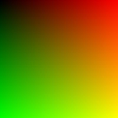
As you can see a RWTexture2D object is used to store the output (this is the UAV). The shader is setup to run 32x32x1 threads. This means that since the CPU is launching 32x32x1 thread groups, then there are 1024x1024x1 separate threads being run. This equates to 1 thread per pixel in the output UAV. So, in the UAV, the color is just set based upon the thread ID.
This code results in the following output image:
Quite simple, eh? But not that interesting. We could easily do something like that with a pixel shader (although we would have to rasterize a full-screen quad to do it).
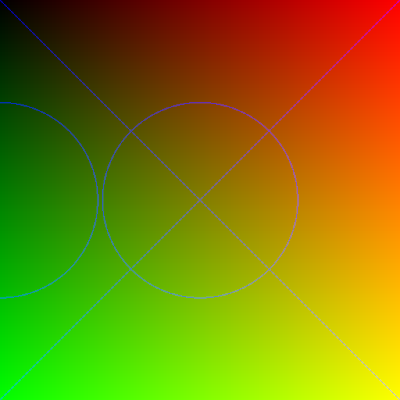
We should try to do something that shows the power of the compute shader; something you couldn't do in a pixel shader before. How about drawing some primitives like lines and circles?
For drawing lines, let's use the Digital Differential Analyzer algorithm. It translates to HLSL very easily.
For drawing circles let's use the Midpoint Circle algorithm. For brevity I won't list it here now.
Then, in my Compute Shader main function, I simply add this code:
The if check is just done to prevent the lines and circles from being drawn for every thread. This code results in the following image:
I must admit it seems quite odd writing a shader that draws primitives. It's like some strange recursive loop. But it definitely helps to illustrate the features of the Compute Shader and how powerful it is.
You may download the source code to this example here:
ComputeShader11.zip
My next goal is to setup a standard DX11 Swap Chain and use the Compute Shader to write directly to the backbuffer. Well that's all for now.
FYI: This is my 50th blog post! I never thought I would continue on this long. I think I should crack open a beer to celebrate.
First let me say that the Compute Shader is awesome! It opens up so many possibilities. My mind is just reeling with new ideas to try out. Also I must mention that SlimDX really does a great job of minimalizing the code necessary to use the Compute Shader.
This example shows how to create a Compute Shader and then use it to launch threads that simply output the thread ID to a texture.
Device device = new Device(DriverType.Hardware, DeviceCreationFlags.Debug, FeatureLevel.Level_11_0);
ComputeShader compute = Helper.LoadComputeShader(device, "SimpleCompute.hlsl", "main");
Texture2D uavTexture;UnorderedAccessView computeResult = Helper.CreateUnorderedAccessView(device, 1024, 1024, Format.R8G8B8A8_UNorm, out uavTexture);
device.ImmediateContext.ComputeShader.Set(compute);
device.ImmediateContext.ComputeShader.SetUnorderedAccessView(computeResult, 0);
device.ImmediateContext.Dispatch(32, 32, 1);
Texture2D.ToFile(device.ImmediateContext, uavTexture, ImageFileFormat.Png, "uav.png");
Believe it or not, but that is the entirety of my CPU code.
Here is what is going on in the code:
1) Create a feature level 11 Device, in order to use Compute Shader 5.0
2) Load/Compile the HLSL code into a ComputeShader object.
3) Create a 1024x1024 UnorderedAccesdView (UAV) object which will be used to store the output.
4) Set the ComputeShader and UAV on the device.
5) Run the Compute Shader by calling Dispatch (32x32x1 thread groups are dispatched).
6) Save the output texture out to disk.
My HLSL code is even simpler:
RWTexture2D<float4> Output;

[numthreads(32, 32, 1)]
void main( uint3 threadID : SV_DispatchThreadID )
{
    Output[threadID.xy] = float4(threadID.xy / 1024.0f, 0, 1);
}
As you can see a RWTexture2D object is used to store the output (this is the UAV). The shader is setup to run 32x32x1 threads. This means that since the CPU is launching 32x32x1 thread groups, then there are 1024x1024x1 separate threads being run. This equates to 1 thread per pixel in the output UAV. So, in the UAV, the color is just set based upon the thread ID.
This code results in the following output image:

Quite simple, eh? But not that interesting. We could easily do something like that with a pixel shader (although we would have to rasterize a full-screen quad to do it).
We should try to do something that shows the power of the compute shader; something you couldn't do in a pixel shader before. How about drawing some primitives like lines and circles?
For drawing lines, let's use the Digital Differential Analyzer algorithm. It translates to HLSL very easily.
void Plot(int x, int y)
{
   Output[uint2(x, y)] = float4(0, 0, 1, 1);
}

void DrawLine(float2 start, float2 end)
{
    float dydx = (end.y - start.y) / (end.x - start.x);
    float y = start.y;
    for (int x = start.x; x <= end.x; x++)
    {
        Plot(x, round(y));
        y = y + dydx;
    }
}
For drawing circles let's use the Midpoint Circle algorithm. For brevity I won't list it here now.
Then, in my Compute Shader main function, I simply add this code:
if (threadID.x == 1023 && threadID.y == 1023)
{
   DrawLine(float2(0, 0), float2(1024, 1024));
   DrawLine(float2(0, 1023), float2(1023, 0));

   DrawCircle(512, 512, 250);
   DrawCircle(0, 512, 250);
}
The if check is just done to prevent the lines and circles from being drawn for every thread. This code results in the following image:

I must admit it seems quite odd writing a shader that draws primitives. It's like some strange recursive loop. But it definitely helps to illustrate the features of the Compute Shader and how powerful it is.
You may download the source code to this example here:
ComputeShader11.zip
My next goal is to setup a standard DX11 Swap Chain and use the Compute Shader to write directly to the backbuffer. Well that's all for now.
FYI: This is my 50th blog post! I never thought I would continue on this long. I think I should crack open a beer to celebrate.
Tuesday, March 9, 2010
Watertight Adaptive Tessellation
The next obvious step for tessellation is to make it adaptive based upon the distance to the camera. It is important to keep the tessellated mesh watertight in order to prevent cracks from appearing between separate quads.
There are five different ways (that I can think of) to address this problem.
1) Do absolutely nothing
For the longest time with my original LOD algorithm this is the path I followed. If you are okay with having nasty cracks in your mesh, then this is definitely the way to go. But that is no longer acceptable to me.
2) Cheap fix (force all edges to be 1)
If all quad edges are not subdivided at all, then there will be no cracks and it will be fast. The problem is there will be no detail at the edges, and this quickly becomes very obvious and ugly.
3) Expensive fix (force all edges to be 64)
Here is the flip-side to the previous option. All quad edges are subdivided to the maximum level. This ensures that the best detail will be used at each edge. However this is too expensive to do for all quads.
4) Be smart about it (use adjacency information)
This is the method that Jack Hoxley uses and describes here. Basically he builds a vertex buffer that contains the 4 vertices of the quad plus another 8 vertices representing the 4 adjacent quads. In the hull shader, he calculates the midpoint of each quad and then calculates the distance (and thus a tessellation factor) from the midpoint to the camera. He chooses the minimum factor for each edge in order to have the quads match.
This is a pretty good solution, but it requires building a large vertex buffer containing adjacency information, as well as the additional midpoint calculation in the hull shader.
5) Do it right (calc factors from each vertex)
The next question is, can we do efficient watertight adaptive tessellation without adjacency information or the midpoint calculation? The answer is yes! If we calculate the tessellation factors from the vertices themselves, then we can guarantee that the surrounding quads will use the same factors (because they are using the same vertices).
The basic algorithm is this:
- Calculate the tessellation factor based on camera distance for each of the 4 vertices
- Use the minimum value for each edge factor (pair of vertices)
- Use the overall minimum value for the inside tessellation factor
Note: I originally thought the inside factor should be the maximum of the 4 vertices, but I after viewing it in action, I felt that the minimum was better.
That's it! Simple, fast, and easy watertight adaptive tessellation.
Check out the video of it in action: (I recorded the video at 1280x720, so be sure to view it at 720 to see the little details.)
There are five different ways (that I can think of) to address this problem.
1) Do absolutely nothing
For the longest time with my original LOD algorithm this is the path I followed. If you are okay with having nasty cracks in your mesh, then this is definitely the way to go. But that is no longer acceptable to me.
2) Cheap fix (force all edges to be 1)
If all quad edges are not subdivided at all, then there will be no cracks and it will be fast. The problem is there will be no detail at the edges, and this quickly becomes very obvious and ugly.
3) Expensive fix (force all edges to be 64)
Here is the flip-side to the previous option. All quad edges are subdivided to the maximum level. This ensures that the best detail will be used at each edge. However this is too expensive to do for all quads.
4) Be smart about it (use adjacency information)
This is the method that Jack Hoxley uses and describes here. Basically he builds a vertex buffer that contains the 4 vertices of the quad plus another 8 vertices representing the 4 adjacent quads. In the hull shader, he calculates the midpoint of each quad and then calculates the distance (and thus a tessellation factor) from the midpoint to the camera. He chooses the minimum factor for each edge in order to have the quads match.
This is a pretty good solution, but it requires building a large vertex buffer containing adjacency information, as well as the additional midpoint calculation in the hull shader.
5) Do it right (calc factors from each vertex)
The next question is, can we do efficient watertight adaptive tessellation without adjacency information or the midpoint calculation? The answer is yes! If we calculate the tessellation factors from the vertices themselves, then we can guarantee that the surrounding quads will use the same factors (because they are using the same vertices).
The basic algorithm is this:
- Calculate the tessellation factor based on camera distance for each of the 4 vertices
float distanceRange = maxDistance - minDistance;
float vertex0 = lerp(minLOD, maxLOD, (1.0f - (saturate((distance(cameraPosition, op[0].position) - minDistance) / distanceRange))));
float vertex1 = lerp(minLOD, maxLOD, (1.0f - (saturate((distance(cameraPosition, op[1].position) - minDistance) / distanceRange))));
float vertex2 = lerp(minLOD, maxLOD, (1.0f - (saturate((distance(cameraPosition, op[2].position) - minDistance) / distanceRange))));
float vertex3 = lerp(minLOD, maxLOD, (1.0f - (saturate((distance(cameraPosition, op[3].position) - minDistance) / distanceRange))));
- Use the minimum value for each edge factor (pair of vertices)
output.edges[0] = min(vertex0, vertex3);
output.edges[1] = min(vertex0, vertex1);
output.edges[2] = min(vertex1, vertex2);
output.edges[3] = min(vertex2, vertex3);
- Use the overall minimum value for the inside tessellation factor
float minTess = min(output.edges[1], output.edges[3]);
output.inside[0] = minTess;
output.inside[1] = minTess;
Note: I originally thought the inside factor should be the maximum of the 4 vertices, but I after viewing it in action, I felt that the minimum was better.
That's it! Simple, fast, and easy watertight adaptive tessellation.
Check out the video of it in action: (I recorded the video at 1280x720, so be sure to view it at 720 to see the little details.)
Thursday, March 4, 2010
Cube to Sphere Tessellation
My previous tessellation example was just a 2D, screen-space quad. My latest example steps into the world of 3D.
No code to share, just a pretty little video. It shows a cube being tessellated on the fly to form a sphere. What's being done is each quad is being tessellated and then the vertex position is normalized.
I was lazy and instead of making an entire cube with 6 sides, I only built a vertex/index buffer for 3 sides. You can only tell when I move the camera around at the end of the video.
I was getting about 1500 fps for the cube and about 900 fps for the fully tessellated sphere. 63*63*3*2 = 23,814 triangles!
Here ya go:
Monday, March 1, 2010
Simple Tessellation Example
I have finally got my computer all setup with the Radeon 5450 and started doing some DirectX 11 development. Obviously the first thing I tried out was the tessellation.
There are some nice sample projects included in the DirectX SDK that cover tessellation, but I felt that they were a little too ... complex. Don't get me wrong, I feel that they are great samples of doing things like model subdivision, detail tessellation, and bezier curves. I just felt that there should be a very simple demonstration of tessellation in the most basic sense. I decided to write one myself and share it here.
I should note that this was written using SlimDX. I love having the power of DirectX in C#!
As I stated, this is pretty much the most basic example of tessellation I could think of. It has one single quad with vertices defined in screen-space, which allows us to skip any transformation. The shader then tessellates the quad by using hard-coded tessellation factors. That's it!

The main application code isn't that important. It just creates the vertex buffer consisting of 4 vertices. It then draws using the new "4 control point patch" primitive. All the rest of the magic happens in the HLSL code.
The vertex shader isn't that impressive. It is simply a pass-through shader and passes the vertex position through to the hull shader.
The hull shader constant fuction simply sets the hard-coded tessellation factors for the edges and inside. Currently I have it hard-coded to a factor of 32. You may manually change this value to be anywhere from 1-64.
The hull shader itself does not perform a basis change, and therefore it passes through all 4 of the input points to the output. As you can see from the attributes, it is operating on the quad domain and it uses the standard clockwise winding.
Before explaining the domain shader, let me first explain the orientation of the UV coordinates coming from the tessellator.
Let's assume your vertices are defined in this manner:
The U dimension ranges from [0-1] in the direction of vertex 0 to vertex 1.
The V dimension ranges from [0-1] in the direction of vertex 0 to vertex 3.
I specifically state this now because I had wrongly assumed that it was oriented such that the U and V coordinates were reversed, like so:
Now, about the domain shader itself. This is normally where the samples got rather complex calculating bezier curves and such. This is the simplest algorithm I could come up with. It uses three linear interpolations to calculate the vertex position. I visualize it as sliding two lines along the the quad and marking where they intersect as the vertex.
The first lerp finds the "midpoint" between vertex 0 and 1 by a factor of U.
The second lerp finds the "midpoint" between vertex 3 and 2 by a factor of U.
The third lerp finds the "midpoint" between the first and second calulated midpoints by a factor of V.
This is rather hard to "draw" a diagram for, but hopefully this makes some sense:
The color of the vertex is set based upon the tessellation UV coordinates.
The pixel shader just writes out the color.
There you have it! Hopefully this simple example of tessellating a single quad will be useful to other people and help to illustrate how the tessellator works.
You can download the full source to this example here: Tessellation.zip
There are some nice sample projects included in the DirectX SDK that cover tessellation, but I felt that they were a little too ... complex. Don't get me wrong, I feel that they are great samples of doing things like model subdivision, detail tessellation, and bezier curves. I just felt that there should be a very simple demonstration of tessellation in the most basic sense. I decided to write one myself and share it here.
I should note that this was written using SlimDX. I love having the power of DirectX in C#!
As I stated, this is pretty much the most basic example of tessellation I could think of. It has one single quad with vertices defined in screen-space, which allows us to skip any transformation. The shader then tessellates the quad by using hard-coded tessellation factors. That's it!

The main application code isn't that important. It just creates the vertex buffer consisting of 4 vertices. It then draws using the new "4 control point patch" primitive. All the rest of the magic happens in the HLSL code.
The vertex shader isn't that impressive. It is simply a pass-through shader and passes the vertex position through to the hull shader.
VS_OUTPUT VS( VS_INPUT input )
{
 VS_OUTPUT output;

 output.position = input.position;

 return output;
}
The hull shader constant fuction simply sets the hard-coded tessellation factors for the edges and inside. Currently I have it hard-coded to a factor of 32. You may manually change this value to be anywhere from 1-64.
HS_CONSTANT_OUTPUT HSConstant( InputPatch<VS_OUTPUT, 4> ip, uint pid : SV_PrimitiveID )
{
 HS_CONSTANT_OUTPUT output;

 float edge = 32.0f;
 float inside = 32.0f;

 output.edges[0] = edge;
 output.edges[1] = edge;
 output.edges[2] = edge;
 output.edges[3] = edge;

 output.inside[0] = inside;
 output.inside[1] = inside;

 return output;
}
The hull shader itself does not perform a basis change, and therefore it passes through all 4 of the input points to the output. As you can see from the attributes, it is operating on the quad domain and it uses the standard clockwise winding.
[domain("quad")]
[partitioning("integer")]
[outputtopology("triangle_cw")]
[outputcontrolpoints(4)]
[patchconstantfunc("HSConstant")]
HS_OUTPUT HS( InputPatch<VS_OUTPUT, 4> ip, uint cpid : SV_OutputControlPointID, uint pid : SV_PrimitiveID )
{
    HS_OUTPUT Output;
    Output.position = ip[cpid].position;
    return Output;
}
Before explaining the domain shader, let me first explain the orientation of the UV coordinates coming from the tessellator.
Let's assume your vertices are defined in this manner:
   u
 0-----1
v|     |
 |     |
 3-----2
The U dimension ranges from [0-1] in the direction of vertex 0 to vertex 1.
The V dimension ranges from [0-1] in the direction of vertex 0 to vertex 3.
I specifically state this now because I had wrongly assumed that it was oriented such that the U and V coordinates were reversed, like so:
  WRONG!
 1-----2
 |     |
v|     |
 0-----3
   u
Now, about the domain shader itself. This is normally where the samples got rather complex calculating bezier curves and such. This is the simplest algorithm I could come up with. It uses three linear interpolations to calculate the vertex position. I visualize it as sliding two lines along the the quad and marking where they intersect as the vertex.
The first lerp finds the "midpoint" between vertex 0 and 1 by a factor of U.
The second lerp finds the "midpoint" between vertex 3 and 2 by a factor of U.
The third lerp finds the "midpoint" between the first and second calulated midpoints by a factor of V.
This is rather hard to "draw" a diagram for, but hopefully this makes some sense:
  lerp1
 0--|--1
 |  _  | lerp3
 |     |
 3--|--2
  lerp2
The color of the vertex is set based upon the tessellation UV coordinates.
[domain("quad")]
DS_OUTPUT DS( HS_CONSTANT_OUTPUT input, float2 UV : SV_DomainLocation, const OutputPatch<HS_OUTPUT, 4> patch )
{
    DS_OUTPUT Output;

    float3 topMidpoint = lerp(patch[0].position, patch[1].position, UV.x);
    float3 bottomMidpoint = lerp(patch[3].position, patch[2].position, UV.x);

    Output.position = float4(lerp(topMidpoint, bottomMidpoint, UV.y), 1);
    Output.color = float4(UV.yx, 1-UV.x, 1);

    return Output;
}
The pixel shader just writes out the color.
float4 PS( DS_OUTPUT input ) : SV_Target
{
 return input.color;
}
There you have it! Hopefully this simple example of tessellating a single quad will be useful to other people and help to illustrate how the tessellator works.
You can download the full source to this example here: Tessellation.zip
Friday, February 19, 2010
Quick Update
DirectX 11
I attended GameFest 2010. I can't say much except that I want to work with DX11 even more than before, if that was possible. As a result, I just bought a Radeon 5450 from newegg. Sure, it is a rather weak card, but it is only $35! Plus, it is much faster than the reference rasterizer and it only consumes 19 watts at full usage!
Here is the card I bought:
http://www.newegg.com/Product/Product.aspx?Item=N82E16814131339
It should hold me over until the Nvidia 400 series cards come out in a month or two.
SlimDX
Talk about perfect timing! The latest version of SlimDX was just released today. The D3D11 wrapper should be even more stable than what it already was.
You can download it from here:
http://slimdx.org/download.php
Subscribe to:
Posts (Atom)